
The Challenge
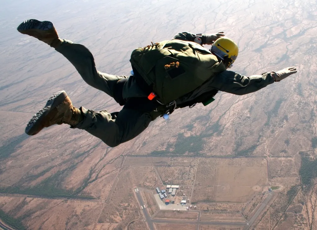
As a skydiver adds more gear such as front packs and items strapped to legs or arms, the jumper’s basic stability in free-fall is reduced. It becomes easier to tumble out of control and there is less margin for error. Similarly, the aerodynamic wake of the jumper may interfere with pilot chute opening (known as “hesitation”). Investigating different gear configurations generally involves vertical wind tunnel testing, or actual tests with jumpers. To avoid some of the cost, and mitigating safety concerns, a tool to computationally analyze these jumpers and their gear is highly desired. Creare, Inc., an R+D research firm in Hanover, NH, under funding from the US Army, developed a Computation Fluid Dynamics toolkit for analyzing jumpers and their equipment, and model the resulting configurations in FlightGear.
Note: a flyable parachutist model is available to download and test at the end of this article.
Fluent (CFD) and Stability Derivatives
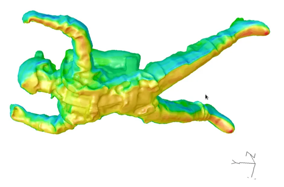
CFD = Computational Fluid Dynamics. ANSYS Fluent is a high end CFD that models flow, turbulence, and heat transfer in 3d. Imagine being able to take a 3d model of a sky diver (or an aircraft) and place it at different orientations and different poses. Then for each orientation and pose, run a computer simulation of exactly how the air flows around the sky diver, where pockets of turbulence are generated, and what forces and moments are produced. Imagine all the combinations of roll and pitch and body poses possible — it leads to a huge number of combinations. Now imagine repeating that for several different arrangements of front and back packs and other equipment. You will need a cluster of computers running for days or even weeks to compute all the permutations just for a single pack configuration. This is essentially a “virtual wind tunnel” running on a super computer cluster of PC’s.
In the case of the parachutist simulation: the amount of computation time required to generate 2 scenarios (with a back pack and without) was approximately 25,000 cpu-hours — or around 2 years of compute time on a single processor PC. 1000 individual simulations were run, each involving approximately 4 million “elements”.
Validation
Real world testing and data collection was performed in a vertical wind tunnel (such as the one linked here.) This real world data could then be compared to the the Fluent (CFD) results to validate and possibly improve the computer model.
Real Time Simulation
Build-Up of Coefficients:
- For each component of the model, the local angle of attack and sideslip angle are calculated from the combination of the limb orientation and the overall angle of attack and sideslip of the entire model.
- For each of the six degrees of freedom, the contribution of the model component to the overall aerodynamic response is calculated from tables of non-dimensional coefficients:
- CFx,y,z = Fx,y,z / ( q∞ * Acomp )
- CMx,y,z = Mx,y,z / ( q∞ Acomp Lcomp )
- The two-dimensional lookup tables are compiled from data extracted from the CFD results in the Solution Database.
Forces and Moments:
- Aerodynamic forces and moments are transformed from the local frame to the global frame and then summed.
- Resultant forces and moments then determine accelerations, velocity and turn rates are calculated, and the model iterates.
Creare partnered with Jon Berndt (the founder of JSBSim–one of the core physics engines used by FlightGear) to contribute some clever additions to JSBSim that permit a “blade element” approach to parachutist modeling. Jon helped tremendously optimizing and integrating the required new code into JSBSim which then ultimately led to its inclusion in FlightGear. The parachutist physics model is an order of magnitude more complex than a typical aircraft model.
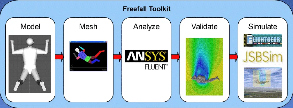
Figure Animation and Posing
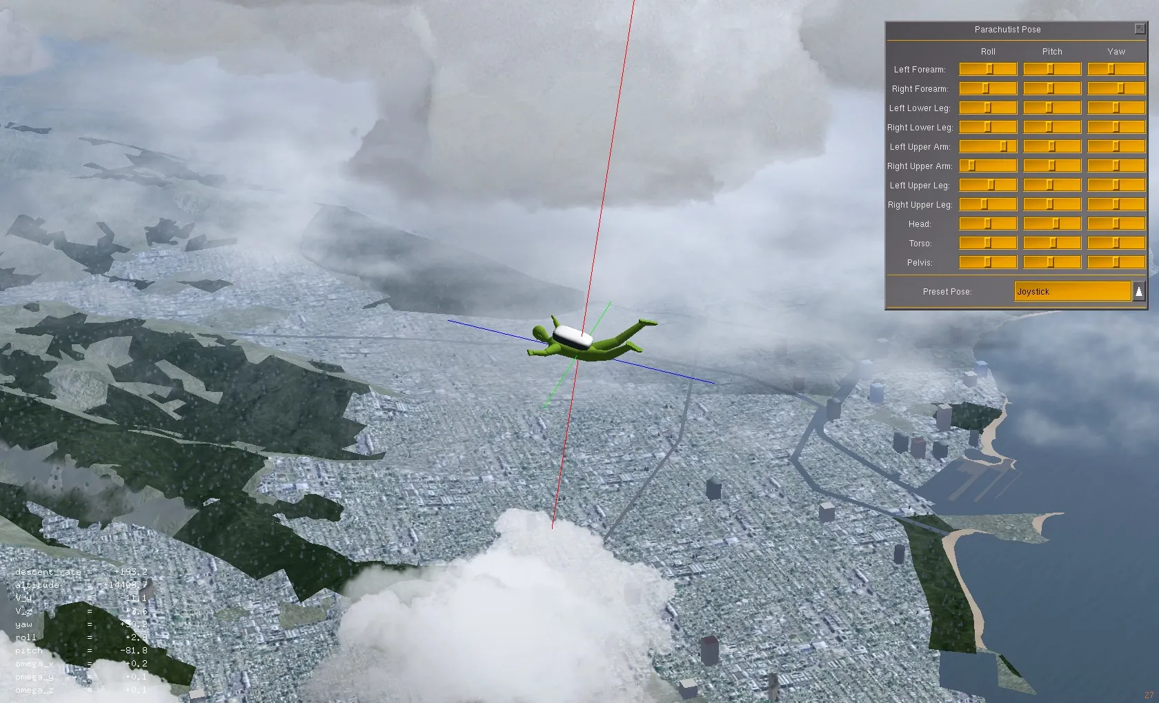
The character model is built out of several animated subcomponents: left & right forearms, left & right upper arms, left & right lower legs, left & right upper legs, head, torso, and pelvis. The model parts are attached in a cascading fashion like a real figure, and each joint can be rotated through all 3 axis (roll, pitch, and yaw.) In order to avoid unrealistic contortions, sensible joint range of motions are defined.
There are a number of predefined poses where the appropriate joint angles have all been worked out in advance.
- Box: a neutral pose minimizing rotational or translational motion.
- Left & Right Translation: mirrored poses that induce a “slide” either to the left or right.
- Anterior Translation: a pose that induces a forward slide.
- Posterior Translation: a pose that induces a rearward slide.
- Left & Right Dorsoventral: mirrored poses that induce a left or right rotation (yaw.)
- Dorsal: a “spread eagle” pose that maximizes surface area and thus minimizes decent rate.
- Ventral: a “compressed” pose that minimizes surface area thus maximizes decent rate.
You might notice that these poses map rather neatly into well understood pilot controls similar to flying a helicopter. For the FlightGear simulation we can mix these poses together in proportion to the corresponding joystick axis deflection and throttle position and fly the sky-diver intuitively. For those that doubt, this actually works quite well! 🙂
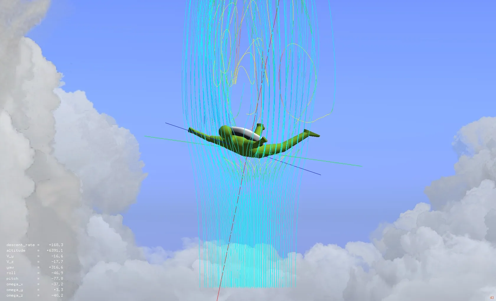
Visualizing CFD Flow-lines
One of the neat things that a CFD analysis can produce are airflow lines that pass around the model. We can take the 3d flowlines that are produced by the CFD and attach them to the 3d model of the figure. This allows visualizing the flow lines from any FlightGear perspective. One interesting technical challenge is that the flow lines need to keep a fixed vertical orientation even though the model may roll or pitch, yet the flowlines must track the heading/yaw of the model. This can be done by setting up appropriate inverse transformations in the FlightGear model animation configuration file.
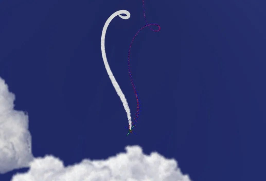
Smoke and Trajectory Markers
FlightGear offers additional visualization aids. The model is set up to support emitting smoke. FlightGear smoke drifts with the prevaling winds (which can often be substantial at higher altitudes.) The model is also setup to emit “trajectory markers” at a fixed rate. The trajectory markers stay fixed in 3d space and represent the actual path the sky diver follows. In addition they represent the orientation of the sky diver at that point in space.
Where is the Parachute?
This exercise is setup as a free-fall simulation, not a parachute simulation so there is no chute modeled. Instead the simulation is mercifully paused when the altitude reaches 100′ above the surface.
Download and Fly
Follow these instructions to download, install, and fly the Creare Parachutist model:
- Note: the parachutist model is not compatible with FlightGear v2.4, you must fly this model with one of the v2.6 release candidates, or the official v2.6 release scheduled for February 17.
- Download the Creare_Parachutist-v1.0.zip file.
- Unzip it into your FlightGear “Aircraft” folder.
- Start FlightGear and select either –aircraft=Parachutist-Scenario1 or –aircraft=Parachutist-Scenario2
- Make sure you specify an initial altitude (such as –altitude=10000), otherwise you will just be sitting at the end of the runway working on your tan.
- Press F1 and F2 to toggle the two available dialog boxes on/off.
- You can manipulate the joint poses individually or select from a set of pre-defined poses, or select “Joystick” control and fly with a joystick (or keyboard or mouse) similar to flying a helicopter or airplane.
Credits
- Dietz, A. J., Kaszeta, R. W., Cameron, B., Micka, D. J., Deserranno, D. and Craley, J.”A CFD Toolkit for Modeling Parachutists in Freefall”, presented at the 21st AIAA Decelerators Conference in Dublin, Ireland, 23-26 May 2011. Paper AIAA 2011-2589.
- The Creare Freefalling Parachutist model was developed by Anthony Dietz (Principal Investigator), Richard Kaszeta , Benjamin Cameron, Daniel Micka, and Dimitri Deserranno of Creare, Inc., as part of an SBIR Phase II project sponsored by the U.S. Army RDECOM Acquisition Center under Contract No. W91CRB-08-C-0135. Additional contributions we made by Curt Olson and Jon S. Berndt as consultants. The resulting parachutist model is unvalidated and therefore, should not be used other than for demonstration purposes. Any opinions, findings and conclusions or recommendations expressed in this material are those of the authors and do not necessarily reflect the views of the US Army RDECOM Acquisition Center. Due to the significant contributions made to the project by several open source developers, Creare has released a version of the resulting parachutist model to the open source community for continued development and use. The FFTK itself continues development as a proprietary Creare project. For information on the FFTK itself, please contact Richard Kaszeta at rwk@creare.com, or 603-643-3800.
- Flightgear modeling, animation, and scripting – Curtis L. Olson