Ocean Debris
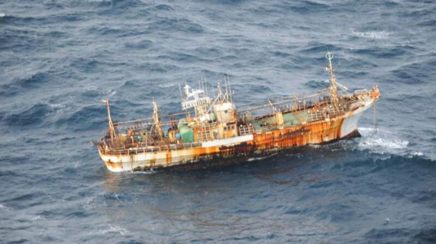
On March 12, 2012 suspected Japanese tsunami debris was discovered washed up on the beaches of Long Beach, CA. On March 11 a deserted fishing vessel was spotted off the coast of British Columbia; by March 24 it had drifted within 120 miles of the coastline. For many years NOAA.gov has been monitoring an every growing area in the North Pacific dubbed the “Great Pacific Garbage Patch” that appears to be collecting and concentrating all manner of plastic debris from all over the world. Whether you are a dedicated environmentalist, or a person that leans more towards managing and sustaining the Earth’s valuable resources indefinitely, or are simply annoyed at having to photoshop garbage out of your pristine vacation pictures; the rapidly increasing amounts of trapped ocean debris should be a concern for everyone. How does any of this relate to the FlightGear simulator? Please read on!
What is “Computer Vision?”
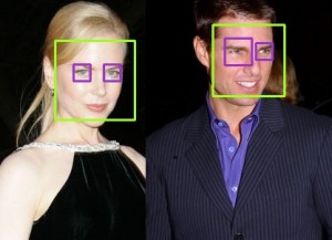
Computer vision is a broad field that involves processing real world images or video to try to automatically extract data or intelligence. Applications range from identifying items or features of interest (such as facial recognition) to extracting geometry and physically locating or reconstructing the layout of a scene to manipulating images in clever or useful ways. In many ways computer vision is a fascinating and magical area. We all have seen software programs that can identify every picture of our Aunt Tina on our computer after we’ve identified her face in one or two pictures. There are computer vision systems that can track people or objects that move through a network of many camera views; computer vision systems can estimate your head orientation and even figure out what direction you are looking or what object you are looking at.. Computer vision software can recognize cars, read printed text, and scan for subtle features hidden in images — and because these programs are automated, they can run around the clock and process vast amounts of imagery. They never get fatigued, they never get bored, and they never start day dreaming about their weekend plans.
Developing a Computer Vision Application
Writing an application to do computer vision is similar to writing any other application. The basic cycle of edit, compile, test, repeat exists like with any other program. Computer vision algorithms apply logical rules and procedures to the image data in consistent ways to accomplish their tasks. There really isn’t any magic, even though the results do seem magical when they outperform the abilities or pace of a human. However, it can be a challenge to develop some computer vision applications if you do not have good access to the kind of imagery you plan to ultimately be processing.
As you can imagine, computer vision applications must deal with huge volumes of data. Often they process live video data from multiple cameras and that data may need to be associated with other data sources in real time — something that may not be possible to test in a lab with prerecorded video.
Imagine you are developing an application which will process aerial imagery to extract some data (i.e. facial recognition) or locate and track items of interest (i.e. a big chunk of debris in the ocean.) It could very likely be the case that you do not have much sample video to test with. In the case of ocean debrid, it may be that you do have video from the correct altitude or taken at the correct air speed, or with the correct camera field of view or camera angle. However, computer programs are most efficiently developed in the lab with repeatable test data and not in the field with whatever random imagery the day offers — this can lead to a disconnect between what imagery is needed for effective testing and what imagery is available.
Hunting and Tracking Ocean Debris
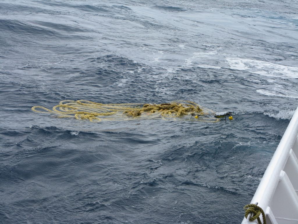
For several years I have been involved with a company that develops UAV’s and remote sensing and tracking systems for marine survey and research use. One of our primary partners is NOAA.gov. NOAA has a keen interest in understanding, tracking, and ultimately cleaning up debris in the ocean. With the Japanese Tsunami last year, the issue of debris accumulating in our oceans has become even more important and critical, yet there is no effective strategy available for locating and removing debris from the ocean.
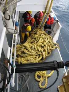
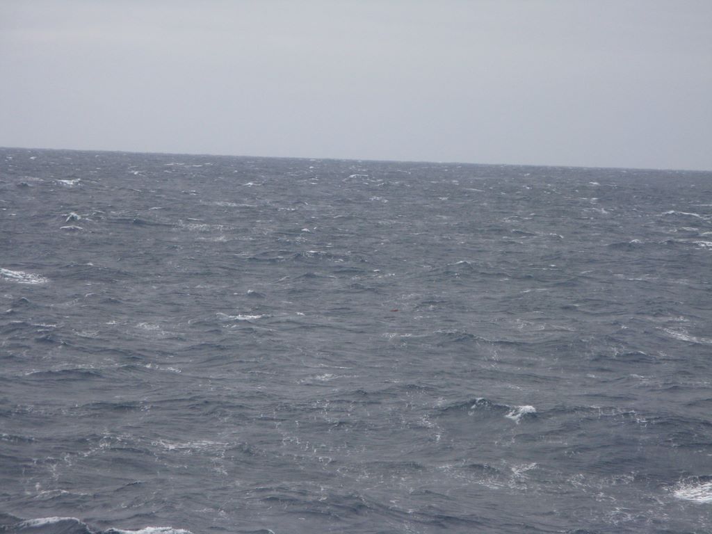
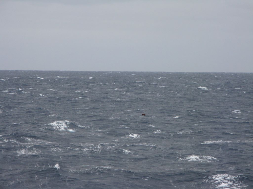
A satellite can survey huge areas, but not at the detail to identify specific pieces of debris. A manned aircraft can fly at several hundred kts and cover a wide area at a low enough altitude to spot individual pieces of debris, but there is nothing you can do when debris is located. A ship travels very slowly and has a very narrow range of view for onboard spotters. A ship might do 10 kts (give or take) and with binoculars a human might be able to spot debris one or two miles away — if they are looking in the right direction at the exact moment a swell lifts the debris up into view in front of the nearer swells. The upper decks of a ship offer some height for observing debris, but swells hide objects more than they reveal them. You have to be looking in the right direction at the right time to even have a chance to spot something. In addition to all the other challenges of ship-board debris spotting, the rolling/pitching motion of the ship makes the use of binoculars very difficult and very fatiguing.
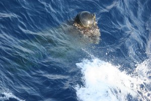
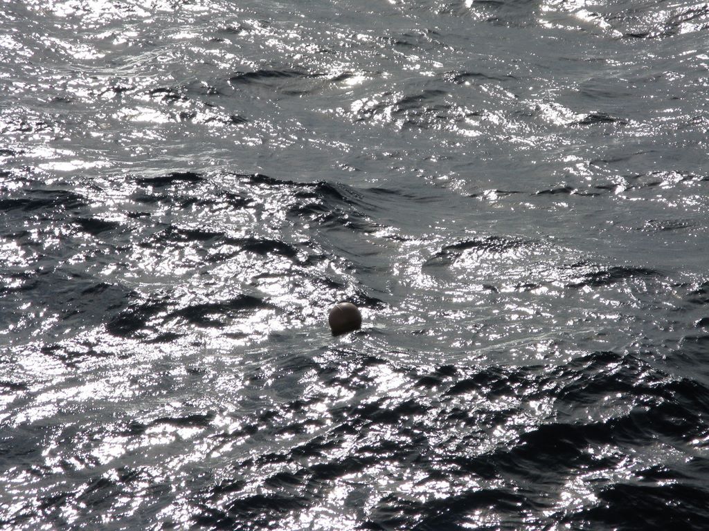
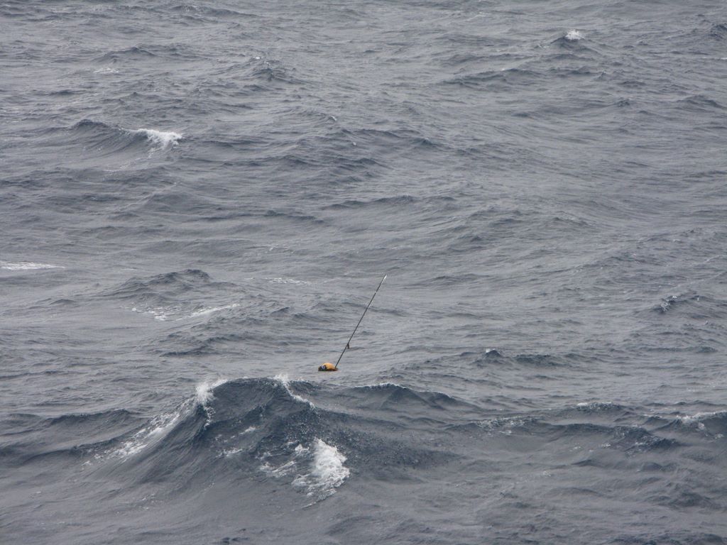
The following two pictures were taken seconds apart. Can you spot the debris in the first image? In the second? (You can click on them to see the full size version.)
A UAS offers numerous advantages over a human operator searching from the highest deck of a ship. The UAS offers a much higher altitude perspective looking downward so that swells and waves can’t hide objects. The UAS offers faster speeds to visually cover more area in the same amount of time. The UAS can carry a variety of image sensors including IR cameras or multi-spectral cameras which offer increased ability to reliably detect certain types of objects under a variety of conditions. Add computer vision software to process the UAV’s imagery and an effective debris location and tracking system begins to emerge.
The UAS has limited range though; and if a significant object is detected, it has no ability to tag or recover the object. Thus it is important to combine UAV operations with a ship in the vicinity to support those UAV operations and be able to take action when something is found.
Visual Challenges of Computer Vision in a Marine Environment
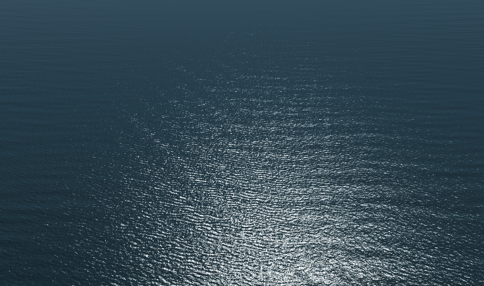
As with any computer vision application, narrowing the scope and focus of the application as much as possible makes solving the problem easier. Using the example of a UAV flying over the ocean and collecting imagery from a camera looking straight down, then the camera frame will always be completely filled with a straight-down view of the ocean surface. We assume we don’t have to deal with the horizon, sky, or clouds or nearby coastline. The result is that the ocean for the most part is some shade of blue — that is convenient. Anything that is not blue is not ocean and then becomes highly interesting. But despite limiting the scope of the problem in this way, the computer vision application still has to deal with several significant challenges: 1. Sun glint — the sun reflecting back at us off the water. 2. Windy days in excess of 12-15 kts produces breaking waves, foam, and even streaking (lines of foam) on the water. Visually, sun-glint and foam impair our ability to spot objects in the water.
Why use FlightGear instead of real camera imagery?
FlightGear generates realistic views of the earth and offers complete control over the altitude, speed, camera orientation, and field of view of a simulated flight. In addition, FlightGear can provide flight telemetry data and other data that is useful for testing or simulating real world environments. We can also control the time of day, clouds, wind, precipitation and fly missions anywhere we like. With FlightGear’s scripting engine, it’s possible to stage static or dynamic scenarios to create the sort of test cases we expect to be able to ultimately handle. Of course only a small slice of computer vision applications relate to processing aerial imagery, but as UAV’s begin to attract the attention of more and more civilian and private organizations, the need for automatically processing huge volumes of imagery data will only increase.
FlightGear “Synthic Imagery” vs. real world camera imagery
As FlightGear continues to develop and evolve, the quality and realism of it’s graphics also are improving. In the most recent version we have taken significant strides forward in drawing realistic ocean scenes that include accurate coloring, accurate rendering of different sea states and types of waves, very realistic sun glint, realistic sea foam (the result of breaking waves on windy days), and even rolling wake and foam created by large ships. The quality of FlightGear ocean scenes can now (in many cases) make them almost indistinguishable from real camera imagery.
What is OpenCV?
OpenCV is a library of data structures and functions that offers most basic image processing tasks, as well as many of the more common advanced functions. OpenCV provides the building blocks a developer needs in order to start writing a computer vision application. OpenCV runs on Linux, Windows, Mac, and even Android.
How to connect an image processing application to FlightGear in “real time”.
Disclaimer: the nuts and bolts that I explain in this section are focused on the Linux platform. These same tools are likely available on other platforms and may be leveraged in the same (or similar) ways to accomplish the same thing — but outside Linux your mileage may vary as they say.
I know how to capture a portion of my desktop as a movie and save it to a file. My computer vision application knows how to read a movie file and process it frame by frame. What is missing is that I want to be able to do this in real time without having to fly and save the video and the process it later. My basic strategy is to first create a unix file system “fifo”, then write the captured video to this fifo, and simultaneously read from the other end of the fifo into my computer vision application.
- Start FlightGear at your simulated camera resolution. I have a cheap web cam that does basic vga (640×480) video, so using that as my “standard” I can run: “fgfs –geometry=640×480” to launch flightgear with the correct window size. Next I drag the FlightGear window into the upper left corner of my screen so it is in a known location.
- Make your fifo if it doesn’t already exist. For instance: “mkfifo /tmp/ffmpeg-fifo.avi”
- Start up the computer vision application: “my-vision-app –infile /tmp/ffmpeg-fifo.avi”
- Start up the ffmpeg desktop movie capture utility (I have a little script I setup so I don’t have to remember all these options every time): “ffmpeg -f alsa -i default -f x11grab -s 640×480 -r 15 -b 200k -bf 2 -g 300 -i :0.0+1,58 -ar 22050 -ab 128k -acodec libmp3lame -vcodec mjpeg -sameq -y /tmp/ffmpeg-fifo.avi”
That’s all it takes and the computer vision application is up and processing live FlightGear generated imagery. One thing I discovered with fifo’s.: it seems to work best to start the reader (the CV app) before starting the writer (ffmpeg). This way the buffers don’t fill up and cause delays.
Results
Here is a snapshot of the anomaly detection and tracking in action:
The original image:
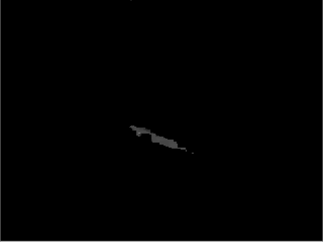
The image partitioned into water vs. not-water.
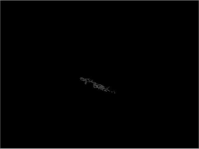
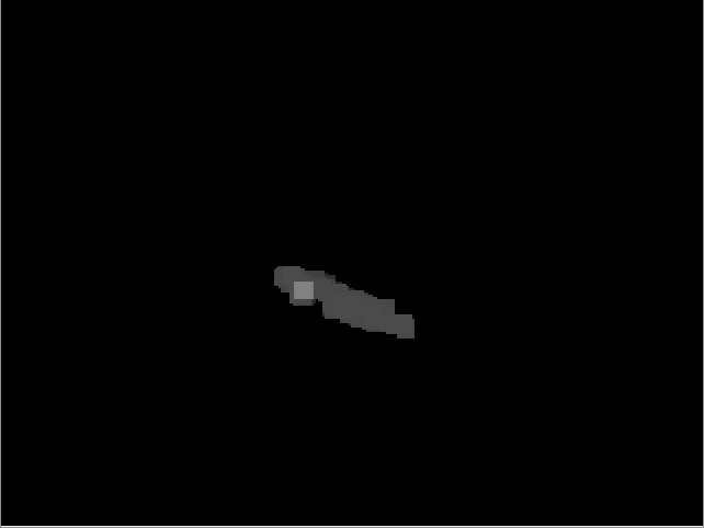
Dilating the mask (connects the noisy dots):
Eroding the dilated mask (to shink it back to approximately the original size and location in the image):
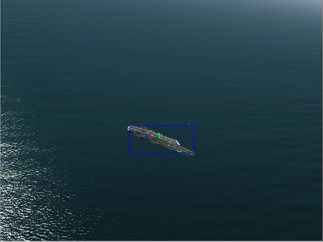
The final composite image showing the detected blob on top of the original frame:
Lastly, here is a youtube video showing all the pieces working together. In FlightGear: I have created a random debris field scattered across an area of open ocean about 6nm x 6nm. I have added a downward looking camera to my test aircraft. Then I built a route that flew several “transacts” (straight line paths) through the debris field. I used the above mentioned procedure to feed the live FlightGear imagery into my computer vision algorithm that detects and tracks anomalies. The debris you tend to see from the air looks very small — usually just a few pixels at best in your image, so the algorithm needs careful tuning to avoid false positives and missing objects.
[youtube]fDPY1PtnBtU[/youtube]
Please watch this video in full screen resolution so you can see the specks of debris and the tracking algorithm in action!
